

Drawing with distance
A triangle on the GPU is three corners and a rule for filling the space between them. That covers anything with corners. A circle has none, and neither does the soft bridge where a circle melts into a star.
This tutorial draws shapes the other way around. Every pixel runs the same small function and answers one question for itself: how far am I from the shape? The sign of the answer says inside or outside. Its size says how far. With that one number we draw a circle, a box and a star, merge them, paint them with contour lines, and set them moving with time and the pointer. The last step rebuilds the Shapes demo from the playground, the live editor on this site.
The Hello, million triangles! page comes first, and this one assumes you know what Shader::new, set and render do.
Every pixel gets a coordinate
Section titled “Every pixel gets a coordinate”A fragment shader runs once per pixel it covers, so the first job is to cover all of them. One oversized triangle does it. Its corners sit at (-1, -1), (3, -1) and (-1, 3) in the [-1, 1] space from the hello triangle tutorial, and its long edge runs exactly through the canvas corner at (1, 1), which puts the whole canvas inside it. The GPU clips the parts that hang off the edges and runs the fragment stage for every pixel that’s left.
@group(0) @binding(0) var<uniform> resolution: vec2<f32>;
// One triangle, big enough to cover the whole canvas.@vertexfn vs_main(@builtin(vertex_index) i: u32) -> @builtin(position) vec4<f32> {    var corners = array<vec2<f32>, 3>(        vec2<f32>(-1.0, -1.0),        vec2<f32>(3.0, -1.0),        vec2<f32>(-1.0, 3.0),    );    return vec4<f32>(corners[i], 0.0, 1.0);}
Every later step keeps this vertex stage and changes only the fragment stage.
The vertex stage writes @builtin(position) in that [-1, 1] space. By the time the fragment stage reads it, the GPU has converted it to pixels: xy counts from the top left corner of the canvas, with y growing downward. The GPU samples each pixel at its center, so on an 800 by 600 canvas the top left pixel reads (0.5, 0.5) and the bottom right one reads (799.5, 599.5).
Pixels make an awkward unit for drawing. A circle 100 pixels wide spans a third of a 300 pixel canvas and a fortieth of a 4K monitor. We want coordinates that look the same on any canvas, and center builds them in three moves:
// Moves the origin to the middle of the canvas,// turns y to point up, and scales the shorter side to one unit.fn center(pixel: vec2<f32>) -> vec2<f32> { let p = (pixel - 0.5 * resolution) / min(resolution.x, resolution.y); return vec2<f32>(p.x, -p.y);}- Subtracting half of
resolutionmoves the origin to the middle of the canvas. - Dividing by the shorter side makes that side one unit long, from
-0.5to0.5. Both axes divide by the same number, which keeps a unit along x as long as a unit along y. The longer side gets whatever range is left:-0.67to0.67across an 800 by 600 canvas. - Negating y makes up positive, the way a math textbook draws its axes.
center.That gives p. Where both of its coordinates run from -0.5 to 0.5 lies the unit square, which always fits the canvas exactly along the shorter side. Painted as a color, p.x drives red and p.y drives green, at full strength inside the unit square and at 30 percent past its edges.
@fragmentfn fs_main(@builtin(position) pixel: vec4<f32>) -> @location(0) vec4<f32> { let p = center(pixel.xy); var color = vec3<f32>(0.5 + p.x, 0.5 + p.y, 0.5); if max(abs(p.x), abs(p.y)) > 0.5 { color = color * 0.3; } return vec4<f32>(color, 1.0);}The bright square keeps its shape at any window size, and only the dim margins grow. Dividing x by the width and y by the height would have stretched it, the way the hello triangle did before its tutorial fixed the aspect ratio.
On the host, setup builds the shader once from SHADER, the string that holds the WGSL above:
let shader = Shader::new(SHADER)?;const shader = new Shader(SHADER);shader = Shader(SHADER)let shader = try Shader(SHADER)val shader = Shader(SHADER)and frame runs on every redraw, with size holding the canvas size in pixels as [width, height]:
shader.set("resolution", size)?;renderer.render(shader, target)?;shader.set("resolution", size);renderer.render(shader, target);shader.set("resolution", size)renderer.render(shader, target)try shader.set("resolution", size)try renderer.render(shader, target)shader.set("resolution", size)renderer.render(shader, target)Something has to call them. In the Rust programs, a small winit loop calls frame whenever the window needs a new image, and on this page each demo canvas does the same. The playground’s programs use this layout too. From step to step, the shader changes and the list of uniforms grows, while the loop stays put. Each step’s complete Rust program and its JavaScript port are in docs/tutorials/drawing-with-distance, and this command runs the first one:
./fc example tutorial_drawing_with_distance_coordinatesOne line of fs_main already measures a distance. max(abs(p.x), abs(p.y)) is the distance from the middle along whichever axis reaches farther, which makes it 0.5 all around the edge of the unit square. Comparing it with 0.5 decides inside or outside. That line holds the whole idea of this tutorial.
A circle is a distance
Section titled “A circle is a distance”length(p) is the distance from p to the origin. Subtracting a radius from it gives a circle:
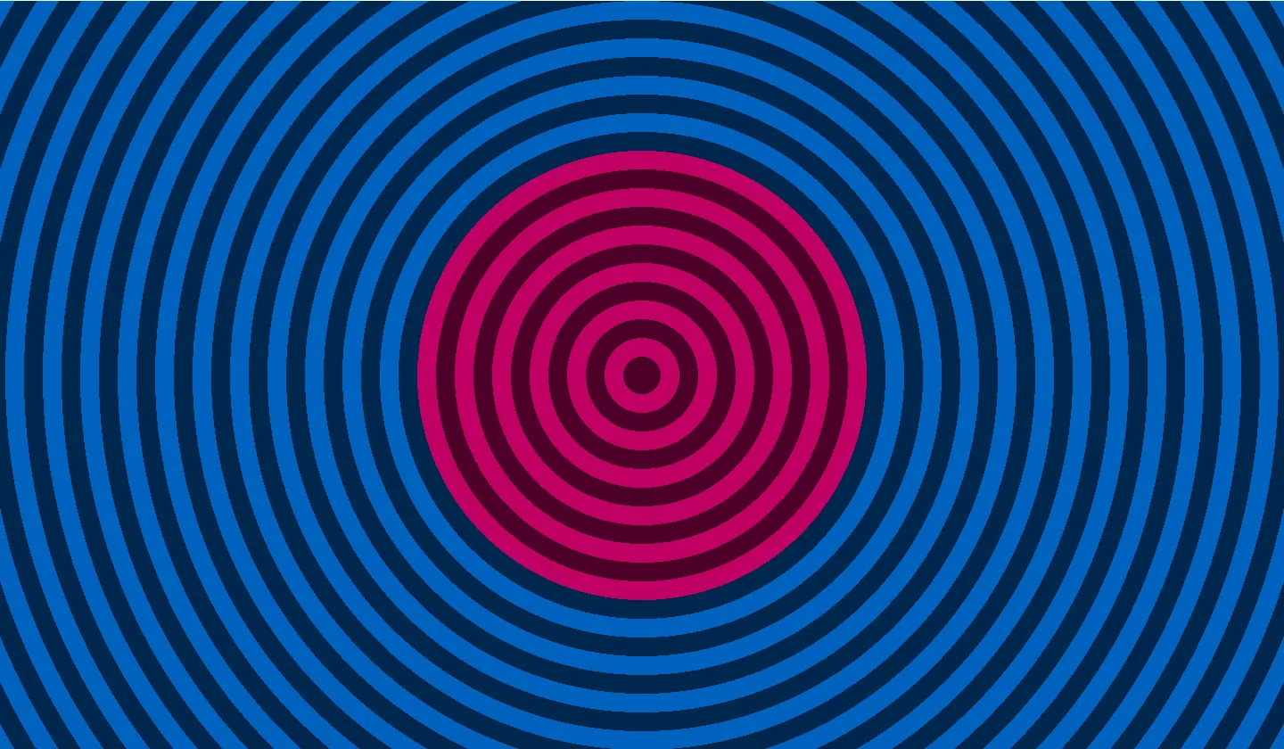
@fragmentfn fs_main(@builtin(position) pixel: vec4<f32>) -> @location(0) vec4<f32> { let p = center(pixel.xy); let d = length(p) - 0.3; return vec4<f32>(show(d), 1.0);}Points on the circle get 0.0. Inside, the numbers turn negative and bottom out at -0.3 in the center; outside, they keep growing toward the corners of the canvas. The size of d is how far p lies from the circle’s outline, and its sign tells you which side you’re on. A function that gives that signed number for every point of the plane is a signed distance field, or SDF.
To see the field, show paints the sign and adds a stripe every 0.05 units of distance:
// Magenta inside, azure outside, and a stripe every 0.05 units of distance.fn show(d: f32) -> vec3<f32> { let tint = select(vec3<f32>(0.0, 0.514, 1.0), vec3<f32>(1.0, 0.0, 0.514), d < 0.0); let stripe = step(0.5, fract(d * 20.0)); return tint * (0.3 + 0.45 * stripe);}select(a, b, condition) returns b where the condition holds and a elsewhere, which paints magenta where d is negative. Every 0.05 units, fract(d * 20.0) climbs from 0.0 to 1.0. step(0.5, x) is 0.0 while x stays below 0.5 and 1.0 after, and it turns each climb into a dark half and a light half.
Magenta meets azure exactly where d crosses zero. That line is the circle.
Six dark stripes run from the edge to the center, one for every 0.05 of the radius. Outside, the rings keep their spacing all the way to the borders of the canvas, and counting them back from any spot to the outline reads off that spot’s distance.
A circle moves when the point does: length(p - c) - r is a circle of radius r centered on c. Every shape on this page measures from p minus its position. Size works in reverse. Dividing p by 2.0 before measuring draws the circle twice as large, and multiplying the result by 2.0 keeps it a true distance: (length(p / 2.0) - r) * 2.0.
The shader library ships this function as sdf2d/circle:
fn circle(p: vec2<f32>, r: f32) -> f32 { return length(p) - r;}From here on we import it by slug, the way the hello triangle tutorial imported noise/simplex2.
Corners: a box and a star
Section titled “Corners: a box and a star”A box makes the question harder, because the nearest point might lie on an edge or on a corner. Symmetry does most of the work. A box centered on the origin looks the same in all four quarters of the plane, so abs(p) folds every point into the top right quarter, and the function only has to handle that one.
// Signed distance to a box centered on the origin.// half_size holds half its width and half its height.fn box(p: vec2<f32>, half_size: vec2<f32>) -> f32 { let q = abs(p) - half_size; let outside = length(max(q, vec2<f32>(0.0))); let inside = min(max(q.x, q.y), 0.0); return outside + inside;}q says how far the point sits past the right edge (q.x) and past the top edge (q.y). A negative value means it hasn’t reached that edge yet.
- Outside the box, at least one of them is positive.
max(q, vec2<f32>(0.0))zeroes the negative one, and thelengthof what’s left is the distance to the nearest edge, or to the corner when both are positive. - Inside, both are negative. The nearest edge is the one with the larger value,
max(q.x, q.y), and wrapping it inmin(..., 0.0)silences that term outside the box.
At any point one of the two terms is zero, and the sum is the other one.
Inigo Quilez publishes this form of the box, with exact distances for dozens of other shapes and a live example for each, on his page of 2D distance functions. The history at the end of this page tells how the technique reached shaders.
The star repeats the trick twice. Rotating by whole arm angles brings every point into the wedge of a single arm, and mirroring across that arm’s middle line leaves one straight edge to measure. Its exact distance is Quilez’s own derivation, and the shader library includes his version as sdf2d/star. It takes star(p, r, n, m). r is the distance from the center to each tip, and n counts the arms as a u32, which is why the call below writes 5u. m runs from 2.0 to n: at 2.0 the star is a plain pentagon, and larger values carve the valleys deeper.
Keeping the smaller of the two distances draws both shapes at once. The next section shows why min works.
@fragmentfn fs_main(@builtin(position) pixel: vec4<f32>) -> @location(0) vec4<f32> { let p = center(pixel.xy); let d_box = box(p - vec2<f32>(-0.25, 0.0), vec2<f32>(0.2, 0.15)); let d_star = star(p - vec2<f32>(0.25, 0.0), 0.2, 5u, 3.0); let d = min(d_box, d_star); return vec4<f32>(show(d), 1.0);}The box you wrote and the imported star end up in the same program. setup names the slug next to the WGSL:
let shader = Shader::new(["sdf2d/star", SHADER])?;const shader = await Shader.fetch(["sdf2d/star", SHADER]);shader = Shader(["sdf2d/star", SHADER])let shader = try Shader(["sdf2d/star", SHADER])val shader = Shader(listOf("sdf2d/star", SHADER))Rust, Python, Swift and Kotlin read slugs from a copy of the shader library built into FragmentColor. In the browser they come over the network, so JavaScript calls Shader.fetch, which downloads the slugs before it compiles the shader.
Next to each shape the stripes copy its outline, pointed around the star and square around the box. Farther out the corners soften. Seen from far enough away, any shape shrinks to a point, and its rings approach circles. Inside the box, the stripes nest as smaller rectangles. Each rectangle’s corners sit on a 45 degree line from a corner of the box, where two edges are equally close. Between the two shapes, the rings from each side meet along a seam. That seam is where the star becomes the closer of the two.
Combining shapes
Section titled “Combining shapes”min works because of what the sign means. A point lies inside the union of two shapes when it is inside either one, and the smaller of two numbers is negative whenever at least one of them is. Outside both shapes, the smaller value belongs to the nearer shape, which makes it the distance to the union. With max, the result goes negative only where both distances are: the intersection. max(a, -b), with one sign flipped, keeps the parts of a that lie outside b, which subtracts b from a.
The shader library names these three op_union, op_intersect and op_subtract. Each one is the single line above. They are in sdf/, next to the 3D shapes, because they combine distances of any dimension.
A union leaves a sharp crease where two outlines cross. op_smooth_union(a, b, k), the quadratic form of Quilez’s smooth minimum, replaces it with a curve:
fn op_smooth_union(a: f32, b: f32, k: f32) -> f32 { let h = clamp(0.5 + 0.5 * (b - a) / k, 0.0, 1.0); return mix(b, a, h) - k * h * (1.0 - h);}h compares the two distances, and clamp keeps it between 0.0 and 1.0. mix(b, a, h) moves from b to a as h grows. When one shape is closer by more than k, h hits one of its limits and mix returns the plain minimum. Inside that margin, mix blends them and k * h * (1.0 - h) takes away a little more, most of all where the distances are equal. Subtracting from d where the outlines meet pushes the zero line outward, and the corner turns into a curve about k units wide.
The next picture holds one circle and one box in each quarter of the unit square, combined four different ways. vec2<f32>(0.11) repeats one value in both components, which makes the box square.
// The two shapes of one pair, measured from the middle of its quarter.fn disc(q: vec2<f32>) -> f32 {    return circle(q - vec2<f32>(-0.07, 0.05), 0.1);}
fn square(q: vec2<f32>) -> f32 { return box(q - vec2<f32>(0.04, -0.03), vec2<f32>(0.11));}@fragmentfn fs_main(@builtin(position) pixel: vec4<f32>) -> @location(0) vec4<f32> { let p = center(pixel.xy);
// Each quarter of the unit square holds one pair, combined its own way. let upper_left = p - vec2<f32>(-0.25, 0.25); let upper_right = p - vec2<f32>(0.25, 0.25); let lower_left = p - vec2<f32>(-0.25, -0.25); let lower_right = p - vec2<f32>(0.25, -0.25);
let joined = op_union(disc(upper_left), square(upper_left)); let overlap = op_intersect(disc(upper_right), square(upper_right)); let carved = op_subtract(square(lower_left), disc(lower_left)); let blended = op_smooth_union(disc(lower_right), square(lower_right), 0.08);
let d = min(min(joined, overlap), min(carved, blended)); return vec4<f32>(show(d), 1.0);}joined, upper left: the union.overlap, upper right: only the part where circle and box meet.carved, lower left: the box minus the circle.blended, lower right: the smooth union, withkat0.08.
One more min, on the last line of fs_main, gathers the four into one picture.
This step imports the circle and the box from the library, along with the operations. sdf2d/box is the function you wrote, under the same name:
let shader = Shader::new([ "sdf2d/circle", "sdf2d/box", "sdf/op_union", "sdf/op_intersect", "sdf/op_subtract", "sdf/op_smooth_union", SHADER,])?;const shader = await Shader.fetch([ "sdf2d/circle", "sdf2d/box", "sdf/op_union", "sdf/op_intersect", "sdf/op_subtract", "sdf/op_smooth_union", SHADER,]);shader = Shader([ "sdf2d/circle", "sdf2d/box", "sdf/op_union", "sdf/op_intersect", "sdf/op_subtract", "sdf/op_smooth_union", SHADER,])let shader = try Shader([ "sdf2d/circle", "sdf2d/box", "sdf/op_union", "sdf/op_intersect", "sdf/op_subtract", "sdf/op_smooth_union", SHADER,])val shader = Shader(listOf( "sdf2d/circle", "sdf2d/box", "sdf/op_union", "sdf/op_intersect", "sdf/op_subtract", "sdf/op_smooth_union", SHADER,))The two unions differ where the outlines cross. In the upper left, the circle meets the box at two sharp notches; in the lower right, the notches fill with curves. Inside the bite of the subtraction, the rings circle the center of the missing disc.
min, max and op_subtract keep the zero line and the sign exact. Away from the edge the number can fall short of the true distance, inside a union for instance. Outlines read only the zero line. The fill gradient in the next section reads the number itself, and inside a union it can come out slightly off.
Coloring the field
Section titled “Coloring the field”The stripes in show are a debugging view. Quilez shades his examples with soft contour bands; this page lights the field its own way, in the three colors of the FragmentColor logo: magenta, violet and azure. This step draws the star, a box and a small circle set close enough to both that the smooth unions merge all three into one outline. Its setup pulls the shapes and the smooth union from the library:
let shader = Shader::new([ "sdf2d/circle", "sdf2d/box", "sdf2d/star", "sdf/op_smooth_union", SHADER,])?;const shader = await Shader.fetch([ "sdf2d/circle", "sdf2d/box", "sdf2d/star", "sdf/op_smooth_union", SHADER,]);shader = Shader([ "sdf2d/circle", "sdf2d/box", "sdf2d/star", "sdf/op_smooth_union", SHADER,])let shader = try Shader([ "sdf2d/circle", "sdf2d/box", "sdf2d/star", "sdf/op_smooth_union", SHADER,])val shader = Shader(listOf( "sdf2d/circle", "sdf2d/box", "sdf2d/star", "sdf/op_smooth_union", SHADER,))let d_star = star(p - vec2<f32>(-0.25, 0.0), 0.2, 5u, 3.0);let d_box = box(p - vec2<f32>(0.25, 0.0), vec2<f32>(0.13));let d_dot = circle(p, 0.08);let d = op_smooth_union(op_smooth_union(d_star, d_box, 0.12), d_dot, 0.12);Every line that writes color adds one layer:
let magenta = vec3<f32>(1.0, 0.0, 0.514);let violet = vec3<f32>(0.514, 0.0, 1.0);let azure = vec3<f32>(0.0, 0.514, 1.0);let outside = max(d, 0.0);let pixel_size = fwidth(d);
var color = vec3<f32>(0.05, 0.06, 0.08) + azure * 0.45 * exp(-10.0 * outside);let ring = abs(fract(d * 20.0 + 0.5) - 0.5) / (20.0 * pixel_size);color = color + azure * 0.35 * exp(-3.0 * outside) * (1.0 - smoothstep(0.5, 1.5, ring));color = select(color, mix(violet, magenta, smoothstep(0.0, 0.12, -d)), d < 0.0);color = mix(color, vec3<f32>(1.0), 1.0 - smoothstep(0.5 * pixel_size, 1.5 * pixel_size, abs(d)));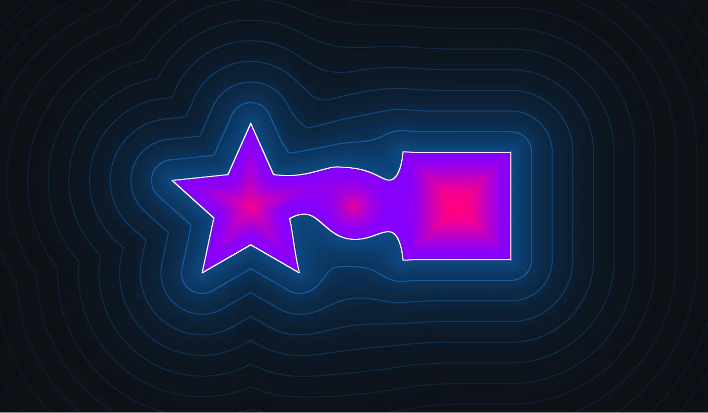
- The backdrop is the site’s near-black.
max(d, 0.0)zeroesdinside the shapes and givesoutside, andexp(-10.0 * outside)is1.0on the edge and drops to a tenth of that about0.23units out, which wraps every outline in an azure glow. pixel_sizeisfwidth(d), how muchdchanges from this pixel to its neighbors: the width of one pixel, measured as a distance.fract(d * 20.0 + 0.5) - 0.5says how fardsits from the nearest multiple of0.05, in units of0.05, and dividing by20.0 * pixel_sizeturns that into pixels.smoothstep(a, b, x)is0.0belowa,1.0aboveband a smooth ramp between.1.0 - smoothstep(0.5, 1.5, ring)therefore keeps only the pixels within about a pixel of a multiple: a thin ring every0.05units. Each ring joins points at the same distance from the shapes, like the height lines on a hiking map, andexp(-3.0 * outside)fades the rings more slowly than the glow.selectswaps everything inside the shapes for a fill.smoothstep(0.0, 0.12, -d)rises from0.0at the edge to1.0at a depth of0.12, andmixturns that into violet by the outline and magenta deep inside.- Mixing toward white by
1.0 - smoothstep(0.5 * pixel_size, 1.5 * pixel_size, abs(d))draws the outline: full white within half a pixel of the edge, gone past one and a half, a line about two pixels wide.
Each layer reads one property of the field. The fill says inside and its gradient how deep, the white line traces the edge, and the glow and the rings give the distance outside. Because both the rings and the outline measure in pixels through fwidth, they stay thin on a phone, on a 4K monitor and at any zoom, and the shader never reads resolution to keep them that way.
Animation takes one more input: the seconds since the program started. It’s a uniform like resolution, at @binding(1):
@group(0) @binding(0) var<uniform> resolution: vec2<f32>;@group(0) @binding(1) var<uniform> time: f32;frame receives the time from its caller and sets it on every redraw, next to the resolution:
shader.set("resolution", size)?;shader.set("time", time)?;renderer.render(shader, target)?;shader.set("resolution", size);shader.set("time", time);renderer.render(shader, target);shader.set("resolution", size)shader.set("time", time)renderer.render(shader, target)try shader.set("resolution", size)try shader.set("time", time)try renderer.render(shader, target)shader.set("resolution", size)shader.set("time", time)renderer.render(shader, target)In the shader, time moves the star and the box:
let d_star = star(rotate2(p - vec2<f32>(-0.25, 0.0), time * 0.4), 0.2, 5u, 3.0);let d_box = box(p - vec2<f32>(0.25, 0.05 * sin(time)), vec2<f32>(0.13));let d_dot = circle(p, 0.08);let d = op_smooth_union(op_smooth_union(d_star, d_box, 0.12), d_dot, 0.12);rotate2(p, a) from map/rotate2 turns a point counterclockwise around the origin by a radians. Applied to every point with time * 0.4 as the angle, it rotates the coordinates the star measures from, which spins the star itself the other way: clockwise, once around in about 16 seconds. 0.05 * sin(time) lifts and lowers the box by 0.05 units on a 6.3 second cycle. With rotate2 in use, the slug list grows by one:
star receives q, the pixel p rotated counterclockwise by a, and the star on screen comes out turned clockwise.let shader = Shader::new([ "sdf2d/circle", "sdf2d/box", "sdf2d/star", "sdf/op_smooth_union", "map/rotate2", SHADER,])?;const shader = await Shader.fetch([ "sdf2d/circle", "sdf2d/box", "sdf2d/star", "sdf/op_smooth_union", "map/rotate2", SHADER,]);shader = Shader([ "sdf2d/circle", "sdf2d/box", "sdf2d/star", "sdf/op_smooth_union", "map/rotate2", SHADER,])let shader = try Shader([ "sdf2d/circle", "sdf2d/box", "sdf2d/star", "sdf/op_smooth_union", "map/rotate2", SHADER,])val shader = Shader(listOf( "sdf2d/circle", "sdf2d/box", "sdf2d/star", "sdf/op_smooth_union", "map/rotate2", SHADER,))The rings move too. Subtracting time inside fract slides each one outward:
let ring = abs(fract(d * 20.0 - 0.5 * time + 0.5) - 0.5) / (20.0 * pixel_size);A ring sits wherever d * 20.0 - 0.5 * time lands on a whole number. As time grows, d has to grow with it, and every ring drifts away from the shapes at 0.025 units per second.
The pointer and the knobs
Section titled “The pointer and the knobs”Two kinds of input remain: the pointer, and six settings to tune by hand. With resolution and time, that makes nine uniforms, enough to gather into a struct. shader.set names a field with a dot: "u.time", "u.pointer".
struct Params {    resolution: vec2<f32>,    pointer: vec2<f32>,    time: f32,    blend: f32, // 0..0.4    rings: f32, // 5..60    glow: f32, // 2..30    inside_color: vec3<f32>,    rim_color: vec3<f32>,    outside_color: vec3<f32>,}
@group(0) @binding(0) var<uniform> u: Params;
Moving resolution into the struct turns each resolution in center into u.resolution:
// Moves the origin to the middle of the canvas,// turns y to point up, and scales the shorter side to one unit.fn center(pixel: vec2<f32>) -> vec2<f32> { let p = (pixel - 0.5 * u.resolution) / min(u.resolution.x, u.resolution.y); return vec2<f32>(p.x, -p.y);}The playground gives a control to every value its setup sets and its frame leaves alone. A // min..max comment after the field, like the ones on blend, rings and glow, becomes the slider’s range, and a vec3<f32> whose name contains color or tint gets a color picker instead. On the GPU the comments do nothing, and in your own program those fields are plain values, set once in setup:
let shader = Shader::new([ "sdf2d/circle", "sdf2d/box", "sdf2d/star", "sdf/op_smooth_union", "map/rotate2", SHADER,])?;shader.set("u.blend", 0.12)?;shader.set("u.rings", 20.0)?;shader.set("u.glow", 10.0)?;shader.set("u.inside_color", [1.0, 0.0, 0.514])?;shader.set("u.rim_color", [0.514, 0.0, 1.0])?;shader.set("u.outside_color", [0.0, 0.514, 1.0])?;const shader = await Shader.fetch([ "sdf2d/circle", "sdf2d/box", "sdf2d/star", "sdf/op_smooth_union", "map/rotate2", SHADER,]);shader.set("u.blend", 0.12);shader.set("u.rings", 20);shader.set("u.glow", 10);shader.set("u.inside_color", [1, 0, 0.514]);shader.set("u.rim_color", [0.514, 0, 1]);shader.set("u.outside_color", [0, 0.514, 1]);shader = Shader([ "sdf2d/circle", "sdf2d/box", "sdf2d/star", "sdf/op_smooth_union", "map/rotate2", SHADER,])shader.set("u.blend", 0.12)shader.set("u.rings", 20.0)shader.set("u.glow", 10.0)shader.set("u.inside_color", [1.0, 0.0, 0.514])shader.set("u.rim_color", [0.514, 0.0, 1.0])shader.set("u.outside_color", [0.0, 0.514, 1.0])let shader = try Shader([ "sdf2d/circle", "sdf2d/box", "sdf2d/star", "sdf/op_smooth_union", "map/rotate2", SHADER,])try shader.set("u.blend", 0.12)try shader.set("u.rings", 20.0)try shader.set("u.glow", 10.0)try shader.set("u.inside_color", [1.0, 0.0, 0.514])try shader.set("u.rim_color", [0.514, 0.0, 1.0])try shader.set("u.outside_color", [0.0, 0.514, 1.0])val shader = Shader(listOf( "sdf2d/circle", "sdf2d/box", "sdf2d/star", "sdf/op_smooth_union", "map/rotate2", SHADER,))shader.set("u.blend", 0.12f)shader.set("u.rings", 20.0f)shader.set("u.glow", 10.0f)shader.set("u.inside_color", listOf(1.0f, 0.0f, 0.514f))shader.set("u.rim_color", listOf(0.514f, 0.0f, 1.0f))shader.set("u.outside_color", listOf(0.0f, 0.514f, 1.0f))Like time, the pointer arrives in frame as an argument, and frame sets it along with the other two inputs that change while the program runs:
shader.set("u.resolution", size)?;shader.set("u.time", time)?;shader.set("u.pointer", pointer)?;renderer.render(shader, target)?;shader.set("u.resolution", size);shader.set("u.time", time);shader.set("u.pointer", pointer);renderer.render(shader, target);shader.set("u.resolution", size)shader.set("u.time", time)shader.set("u.pointer", pointer)renderer.render(shader, target)try shader.set("u.resolution", size)try shader.set("u.time", time)try shader.set("u.pointer", pointer)try renderer.render(shader, target)shader.set("u.resolution", size)shader.set("u.time", time)shader.set("u.pointer", pointer)renderer.render(shader, target)Where the position comes from depends on the platform. In the Rust program, winit reports each cursor move in the window’s physical pixels, and the loop hands the latest one to frame. On this page, each demo listens for pointermove on its canvas, subtracts the element’s position on the page and scales from CSS units to the drawing buffer’s own resolution; the playground’s index.js tab shows that code. Until the pointer first moves over the demo, both supply its middle instead. Python, Swift and Kotlin read the pointer from their own toolkits, such as a rendercanvas pointer_move event, a UIKit touch or an Android MotionEvent, and may need the same conversion to the surface’s pixels.
Pointer positions count from the top left corner with y growing downward, the same space @builtin(position) uses. center converts them like any pixel, and one subtraction parks the circle under the pointer:
@fragmentfn fs_main(@builtin(position) pixel: vec4<f32>) -> @location(0) vec4<f32> {    let p = center(pixel.xy);    let pointer = center(u.pointer);    let t = u.time;
    let d_star = star(rotate2(p - vec2<f32>(-0.25, 0.0), t * 0.4), 0.2, 5u, 3.0);    let d_box = box(p - vec2<f32>(0.25, 0.05 * sin(t)), vec2<f32>(0.13));    let d_dot = circle(p - pointer, 0.08);    let d = op_smooth_union(op_smooth_union(d_star, d_box, u.blend), d_dot, u.blend);
    let outside = max(d, 0.0);    let pixel_size = fwidth(d);    var color = vec3<f32>(0.05, 0.06, 0.08) + u.outside_color * 0.45 * exp(-u.glow * outside);    let ring = abs(fract(d * u.rings - 0.5 * t + 0.5) - 0.5) / (u.rings * pixel_size);    color = color + u.outside_color * 0.35 * exp(-3.0 * outside) * (1.0 - smoothstep(0.5, 1.5, ring));    color = select(color, mix(u.rim_color, u.inside_color, smoothstep(0.0, 0.12, -d)), d < 0.0);    color = mix(color, vec3<f32>(1.0), 1.0 - smoothstep(0.5 * pixel_size, 1.5 * pixel_size, abs(d)));    return vec4<f32>(color, 1.0);}
The circle follows the pointer across the canvas, and whenever it comes within blend of the star or the box, the outlines reach for each other.
The Shapes demo
Section titled “The Shapes demo”The playground’s Shapes demo is this program with a few changes: a hexagon from sdf2d/hexagon in place of the box, the two shapes at x = -0.3 and x = 0.3, and the pointer field named mouse. It also computes p from a value the vertex stage passes down, which gives the same coordinates as center. Its sliders take their ranges from the same // min..max comments. Near 0.4, blend fuses the shapes; at 5, rings leaves a fifth of a unit between neighbors, and the three color pickers recolor the fill, its rim and the glow. The shader.wgsl and main.js tabs are editable and rebuild as you type, the language tabs follow your edits, and + Add brings in more slugs from the shader library.
A circle, a star and a hexagon, the last two from Inigo Quilez's 2D distance functions, merged with his smooth union. The distance lights the scene: an azure glow and drifting rings outside, violet to magenta inside. The circle follows the pointer.
Click to use the keyboard
This demo runs compute shaders, which need WebGPU. This browser is drawing with WebGL2, so it shows a recording. The code is still yours to read and edit.
The playground draws with WebGPU or WebGL2, and this browser could not start either. A recent Chrome, Edge, Safari, or Firefox runs it.
center keeps its job through all seven steps, and only what follows it changes. A pixel goes in as p and comes out as a color, and noise, fractals and lighting fit in the same place.
Where distance fields come from
Section titled “Where distance fields come from”Computing every pixel’s distance to a shape is older than GPUs by decades.
In 1966, Azriel Rosenfeld and John L. Pfaltz described two sweeps over a digital image that find, for every pixel, how far it lies from the nearest pixel of a chosen set (Sequential Operations in Digital Picture Processing). Their distance transform counted pixels on a grid and carried no sign. Moving boundaries made signed distances a standard tool: Stanley Osher and James A. Sethian’s level set method (1988) tracks an interface as the zero level of a function defined all around it, most often the distance to the interface with a sign attached.
John C. Hart turned the distance into a way to render. In 1989 he, Daniel Sandin and Louis Kauffman ray traced 3D fractals, moving along each ray no farther than a safe estimate of how close the fractal could be, and his sphere tracing (1996) generalized the method: a ray from the eye through each pixel advances in steps as long as the distance to the nearest surface, steps that can never overshoot.
Text brought distance fields to everyday screens. At Mitsubishi Electric Research Laboratories (MERL), Sarah F. Frisken, Ronald N. Perry, Alyn P. Rockwood and Thouis R. Jones stored the field finely near edges and coarsely elsewhere (Adaptively Sampled Distance Fields, SIGGRAPH 2000). Perry and Frisken built the Saffron type system on that work, and in 2005 it became the new text renderer of Macromedia Flash Player 8. Two years later, in a SIGGRAPH course, Chris Green of Valve showed that a small distance field texture magnifies into crisp lettering (Improved Alpha-Tested Magnification for Vector Textures and Special Effects); Team Fortress 2 used the method for the words on its signs and for screen overlays. One distance per texel, the texture’s own pixel, blunts the corners. Viktor Chlumský’s 2015 master’s thesis split the field across three channels, and his msdfgen tool keeps glyph corners almost perfectly sharp.
In the same years, real-time shaders took up the idea. Demoscene programmers, who fit whole animations into tiny programs, marched rays through distance fields the way sphere tracing does, and in 2004 Keenan Crane rendered 3D slices of quaternion Julia sets, fractals that live in four dimensions, in a GPU fragment program. Inigo Quilez carried the technique to a wide audience. His NVScene 2008 talk, Rendering Worlds with Two Triangles with raytracing on the GPU in 4096 bytes, explained how 4 KB demos raymarch whole worlds through distance fields. The articles that followed work out the exact 2D distances and the smooth minimum on this page, and in 2013 he and Pol Jeremias created Shadertoy, where people share shaders drawn this way. His article on raymarching distance fields traces that earlier work in detail.
From his catalog this page takes the box and star distances and the smooth minimum. More of his shapes, from the rhombus to the trapezoid, are in the shader library under sdf2d/.